So I've finally got the engine into the car and it's time to start making the custom engine harness that won't make the bay look so hideous.
I've been doing a lot of research the last few weeks and I have a good grasp on what I need to do. Just need some feedback from the wiring pros in-case there is something I missed. I will be running a Gen 2 Megasquirt PNP, I have an extra harness to get ECU connectors from and I've orderd 16 Bosch style plugs and pins. I've also acquired 13 colors of TXL wiring to hopefully knock this out.
I have color coded the schematics to show what will need to be ran, spliced and what is existing.
Blue = Existing
Orange = Splice
Green = New wire to be ran
**You may also note that some of the wires/connectors from the 3rd "A" Connector from the ECU not being highlighted. I do not plan on messing with this group of wires since they do not run through the engine harness.**
Here are my questions.
1. MS does not show to need the ST wire, this seems odd to me but I'm assuming it was just a signal for the factory ECU. Is this correct?
2. Same as above question but with the OX sensor. Since I am installing a wideband I do not need it, correct? I will be wiring it into the DB15 connector.
3. Megasquirt says the following on deleting the AFM. Do I show the correct wires spliced on the diagram? (I don't think it is due to it not having a dash between the BR, or is maybe one of the B-R wires going to the EFI Main Relay?)
"To control the fuel pump, you need to do two things. You need to run a jumper wire between two wires at the AFM first. The GRN/RED wire and the BLUE/RED Wire. Connect these together."
4. On wires E21 & THW they show to connect together (E21 being a ground and THW being the ground side of the sensor). Am I wrong or does this mean I need the single prong connector for the dash gauge and another sensor for the MS? I believe this to be the case since the single prong sensor will not have a ground going to it.
5. All the ground wires used to run to the intake of the engine, I would like to move them to the block so they are hidden. This will be fine as long as I have a ground wire going from the engine to the body of the car correct?
6. Does anyone have a higher resolution of the schematics I have attached below, or know where they have come from? I can't make out half the letters/numbers on it and it would help tremendously with figuring out what I do and do not need for the C plug.
I have also attached the helpful printouts from the MS website concerning what needs to be kept and deleted.
http://i.imgur.com/Cdr8pi8.jpg
http://i.imgur.com/nf51h1J.jpg
http://i.imgur.com/hjeCD9x.jpg
Sorry for just image links, no hosting sites offer re-sizing anymore and this site has a ridiculous limit on size.
Megasquirt/7AGE/Custom harness questions (Wiring Guru help!)
Re: Megasquirt/7AGE/Custom harness questions (Wiring Guru he
Anyone, Bueller?

Re: Megasquirt/7AGE/Custom harness questions (Wiring Guru he
I don't know anything specific about MS but as most ECU's work more or less the same,
here are some generic answers
The ST signal tells the factory ECU the engine is cranking so that it can make changes
to help the engine start. MS should have settings that achieve the same result, probably
based on engine rpm.
The factory ECU uses a narrowband O2 sensor to run closed loop fuel control. If you want
MS to be able to run closed loop, you will need to provide a suitable input from your
wideband O2 controller.
The GRN/RED wire gets connected to the BROWN wire when the flap in the AFM opens and
closes an internal switch i.e. the GRN/RED wire gets switched to ground and energises
the COR to run the fuel pump. If you bridge these two wires the COR will be energised
full time, so you will need to have some means for MS to control the COR.
THW is the ECU water temp sensor and will have two wires, one dedicated MS input
and one sensor ground. The sensor ground may be shared with other 5V sensors, but
do not connect to chassis ground. The sensor for the gauge does not interface with the
ECU and has a single wire. The sensor grounds to the chassis thru the outer case.
NB: THA is inside the AFM so you will need to provide a separate THA as noted.
If you ground on the block follow the MS instructions. You need to keep away from the
starter and alternator. Make sure you have one fat ground wire from beside the starter,
plus one medium wire from the head and one from the block on the intake side.
I'll see if I can find something. Here ya go... best I can do, so hope it helps
https://app.box.com/s/8jyifhvj5y3e9f4jp7yzxafjfnqa73fe
https://app.box.com/s/l9bjya0gaqhzvslafsyb1nrqs7ded0mg
Cheers... jondee86
here are some generic answers
c4ptiv3 wrote:Here are my questions.
1. MS does not show to need the ST wire, this seems odd to me but I'm assuming it was
just a signal for the factory ECU. Is this correct?
The ST signal tells the factory ECU the engine is cranking so that it can make changes
to help the engine start. MS should have settings that achieve the same result, probably
based on engine rpm.
2. Same as above question but with the OX sensor. Since I am installing a wideband I do
not need it, correct? I will be wiring it into the DB15 connector.
The factory ECU uses a narrowband O2 sensor to run closed loop fuel control. If you want
MS to be able to run closed loop, you will need to provide a suitable input from your
wideband O2 controller.
3. Megasquirt says the following on deleting the AFM. Do I show the correct wires spliced
on the diagram? "To control the fuel pump, you need to do two things. You need to run
a jumper wire between two wires at the AFM first. The GRN/RED wire and the BLUE/RED
Wire. Connect these together."
The GRN/RED wire gets connected to the BROWN wire when the flap in the AFM opens and
closes an internal switch i.e. the GRN/RED wire gets switched to ground and energises
the COR to run the fuel pump. If you bridge these two wires the COR will be energised
full time, so you will need to have some means for MS to control the COR.
4. On wires E21 & THW they show to connect together (E21 being a ground and THW
being the ground side of the sensor). Am I wrong or does this mean I need the single
prong connector for the dash gauge and another sensor for the MS? I believe this to be
the case since the single prong sensor will not have a ground going to it.
THW is the ECU water temp sensor and will have two wires, one dedicated MS input
and one sensor ground. The sensor ground may be shared with other 5V sensors, but
do not connect to chassis ground. The sensor for the gauge does not interface with the
ECU and has a single wire. The sensor grounds to the chassis thru the outer case.
NB: THA is inside the AFM so you will need to provide a separate THA as noted.
5. All the ground wires used to run to the intake of the engine, I would like to move
them to the block so they are hidden. This will be fine as long as I have a ground wire
going from the engine to the body of the car correct?
If you ground on the block follow the MS instructions. You need to keep away from the
starter and alternator. Make sure you have one fat ground wire from beside the starter,
plus one medium wire from the head and one from the block on the intake side.
6. Does anyone have a higher resolution of the schematics I have attached below, or
know where they have come from? I can't make out half the letters/numbers on it and
it would help tremendously with figuring out what I do and do not need for the C plug.
I'll see if I can find something. Here ya go... best I can do, so hope it helps
https://app.box.com/s/8jyifhvj5y3e9f4jp7yzxafjfnqa73fe
https://app.box.com/s/l9bjya0gaqhzvslafsyb1nrqs7ded0mg
Cheers... jondee86
The reasonable man adapts himself to the world; the unreasonable one
persists in trying to adapt the world to himself. Therefore, all progress
depends on the unreasonable man.
persists in trying to adapt the world to himself. Therefore, all progress
depends on the unreasonable man.
Re: Megasquirt/7AGE/Custom harness questions (Wiring Guru he
As always, thanks again Jondee86!
Re: Megasquirt/7AGE/Custom harness questions (Wiring Guru he
Getting everything in order to start work on this tomorrow and I think i'm just going to jumper the wires that DIYAUTOTUNE mentions in their article. They both come off the C* plug at the kickpanel and I can just loop them there.
Re: Megasquirt/7AGE/Custom harness questions (Wiring Guru he
I had a look at the PNP install instructions and it definitely does say this...
As far as I can see this will apply 12V to the COR "RUN" coil from the B pin to the A5 (VC)
pin on the OEM ECU whenever the EFI Main Relay is energised. I can only assume that MS
have re-assigned the VC pin to disrupt power to the COR relay if the engine stops. The
"START" coil in the COR is most likely redundant, as no doubt the PNP has start enrichment
to replace the cold start injector.
Bit of confusion in my earlier answer on this point, as I overlooked the fact that wiring
color blue is coded as "L" by Toyota to avoid confusion with "B" for black
Also, I saw in the PNP instructions that MS can control high or low impedence injectors,
so you can delete the injector resistor box.
Cheers... jondee86
To control the fuel pump, you need to do two things. You need to run a jumper wire between
two wires at the AFM first. The GRN/RED wire and the BLUE/RED Wire. Connect these together.
As far as I can see this will apply 12V to the COR "RUN" coil from the B pin to the A5 (VC)
pin on the OEM ECU whenever the EFI Main Relay is energised. I can only assume that MS
have re-assigned the VC pin to disrupt power to the COR relay if the engine stops. The
"START" coil in the COR is most likely redundant, as no doubt the PNP has start enrichment
to replace the cold start injector.
Bit of confusion in my earlier answer on this point, as I overlooked the fact that wiring
color blue is coded as "L" by Toyota to avoid confusion with "B" for black
Also, I saw in the PNP instructions that MS can control high or low impedence injectors,
so you can delete the injector resistor box.
Cheers... jondee86
The reasonable man adapts himself to the world; the unreasonable one
persists in trying to adapt the world to himself. Therefore, all progress
depends on the unreasonable man.
persists in trying to adapt the world to himself. Therefore, all progress
depends on the unreasonable man.
Re: Megasquirt/7AGE/Custom harness questions (Wiring Guru he
jondee86 wrote:I had a look at the PNP install instructions and it definitely does say this...To control the fuel pump, you need to do two things. You need to run a jumper wire between
two wires at the AFM first. The GRN/RED wire and the BLUE/RED Wire. Connect these together.
As far as I can see this will apply 12V to the COR "RUN" coil from the B pin to the A5 (VC)
pin on the OEM ECU whenever the EFI Main Relay is energised. I can only assume that MS
have re-assigned the VC pin to disrupt power to the COR relay if the engine stops. The
"START" coil in the COR is most likely redundant, as no doubt the PNP has start enrichment
to replace the cold start injector.
Bit of confusion in my earlier answer on this point, as I overlooked the fact that wiring
color blue is coded as "L" by Toyota to avoid confusion with "B" for black
Also, I saw in the PNP instructions that MS can control high or low impedence injectors,
so you can delete the injector resistor box.
Cheers... jondee86
Yeah, I had found this in a document when looking at how to delete the AFM. It does look like they have a way to control it.
"Fuel Pump Control:
To control the fuel pump, you need to do two things. You need to run a jumper wire between two wires at the AFM first. The GRN/RED wire and the BLUE/RED Wire. Connect these together.
Next, you need to set the MSPNP so that it sends the fuel pump output to the AFM. You will need to unscrew the lid from the MSPNP. There is a switch on the lowest circuit board marked S1. Place this switch in the down position. If for some reason you need to re-install the AFM, this switch needs to be in the up position."
Being able to delete the resistor box is quite possibly the greatest thing I've ever read, it's a Christmas miracle!
I appreciate all the input, I'll update the diagram in a bit. Thanks Jondee
Re: Megasquirt/7AGE/Custom harness questions (Wiring Guru he
Okay, after talking to Jondee86 I think I have the finalized version of the EFI section of the diagram. I'm still working on the C and C* plug to make sure there is nothing else missing.
Let me know what you think JD
http://i.imgur.com/jXFPXyB.png
Let me know what you think JD
http://i.imgur.com/jXFPXyB.png
Re: Megasquirt/7AGE/Custom harness questions (Wiring Guru he
If you are using your drawing to identify each wire that needs to terminate in
one of the OEM ECU plugs, then you may need to add the following...
Pin B3 = G+ from distributor
Pin B4 = G- from distributor.
These two wires should be shielded. Ground the shield at one end only.
Pin A1 = +B1
Pin A8 = +B
I'm fairly sure that one of these wires originates near the underhood fuse
box and runs the full length of the engine harness.
As you are not showing a connection for the TPS IDL switch, I assume that the
PNP has an alternative method of recognising when the throttle is closed e.g.
when the TPS reading is less than (say) 2% open ?
Otherwise looking good
Cheers... jondee86
The reasonable man adapts himself to the world; the unreasonable one
persists in trying to adapt the world to himself. Therefore, all progress
depends on the unreasonable man.
persists in trying to adapt the world to himself. Therefore, all progress
depends on the unreasonable man.
Re: Megasquirt/7AGE/Custom harness questions (Wiring Guru he
jondee86 wrote:If you are using your drawing to identify each wire that needs to terminate in
one of the OEM ECU plugs, then you may need to add the following...
Pin B3 = G+ from distributor
Pin B4 = G- from distributor.
These two wires should be shielded. Ground the shield at one end only.
Pin A1 = +B1
Pin A8 = +B
I'm fairly sure that one of these wires originates near the underhood fuse
box and runs the full length of the engine harness.
As you are not showing a connection for the TPS IDL switch, I assume that the
PNP has an alternative method of recognising when the throttle is closed e.g.
when the TPS reading is less than (say) 2% open ?
Otherwise looking good
Cheers... jondee86
I have the entire engine harness in my living room floor and the A plug from the ECU was not attached to it and ran inside the car (I assumed). so I decided to not even mess with it unless it somehow runs through the C or C* plug which I plan on tracing out today. It's also showing that G+ and G- are not needed.
as for the IDL switch, the information on the sight shows that it is not needed so I'm taking their word on it.
Re: Megasquirt/7AGE/Custom harness questions (Wiring Guru he
Alright, I believe this is the final version. I just have to double check the C plug pin 2, which goes to a 2 pin blue plug and confirm on the car if it exists or was from the AC.
http://i.imgur.com/Q8ZgJ8Q.png
http://i.imgur.com/Q8ZgJ8Q.png
Re: Megasquirt/7AGE/Custom harness questions (Wiring Guru he
OK... a little bit of confusion for me as you were referring to this "C-plug"...
... and not to the A, B and C plugs on the ECU. In which case the pin that
you have marked as going to the distributor will actually be the tacho wire
from the igniter.
I would have expected the PNP to need the G+ and G- wires for crank angle
sensing, but if it can compute ignition timing by some other method, then
leave them out. Triple check that detail just to 100% sure.
Cheers... jondee86
The reasonable man adapts himself to the world; the unreasonable one
persists in trying to adapt the world to himself. Therefore, all progress
depends on the unreasonable man.
persists in trying to adapt the world to himself. Therefore, all progress
depends on the unreasonable man.
Re: Megasquirt/7AGE/Custom harness questions (Wiring Guru he
Edit: NVM, I read your reply wrong.
That is a typo, it's going to the coil/ignitor connector.
That is a typo, it's going to the coil/ignitor connector.
Re: Megasquirt/7AGE/Custom harness questions (Wiring Guru he
Here's all the data I used. I'm pretty sure it's right. I traced most of it out by hand on my existing harness.
- Attachments
-
- C Star Plug.png (81.88 KiB) Viewed 20671 times
-
- C Star Plug Wipers.jpg (30.34 KiB) Viewed 20671 times
-
- C Plug.jpg (56.68 KiB) Viewed 20671 times
Re: Megasquirt/7AGE/Custom harness questions (Wiring Guru he
Here's what I traced out by hand after using those documents. Only wire I'm somewhat concerned with is the one coming off Pin 2 of the C Plug. It seems to go to a ground like unit over by the brake plunger system. I'm wondering if it's needed. I'll try to post pictures of it tomorrow.
C* Plug
Pin 5 Green Red
Pin 6 Blue Red
Solder together at the C* plug to power on Fuel Pump when Started
Pin 7 Black Red
Splits to 3 locations
1 goes to TVIS (Don’t need)
1 goes to AFM (Deleting)
1 goes to Black single pin plug (Runs to fuse box)
Windshield Wipers
Pin 3 Blue Black
Pin 4 Blue
Pin 8 Blue Yellow
Pin 9 Blue White
Pin 14 Blue Orange
C Plug
Pin 1 Yellow Green (Water Temp)
Goes to single pin water temp sensor
Pin 2 Black Orange (Injector and Coil Power)
Goes to Green plug for Igniter/Coil
Goes to 2 pin blue plug (Possibly to fuse box)
Goes to resistor box plug (This is the wire the injectors will tie into)
Pin 3 Red Black (Back up Light)
Pin 9 Red Light Blue (Back up Light 12v)
Goes to transmission switch
Pin 13 Black (Tach)
Goes to Ignitor/Coil green plug
Pin 14 Black White (Starter signal)
Goes to Starter
Re: Megasquirt/7AGE/Custom harness questions (Wiring Guru he
If it looks like this...
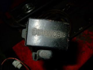
... it will be the diagnosis box. It has wires that link back to various electrical points
to make fault testing a bit easier. You can probably live without it
Cheers... jondee86
... it will be the diagnosis box. It has wires that link back to various electrical points
to make fault testing a bit easier. You can probably live without it
Cheers... jondee86
The reasonable man adapts himself to the world; the unreasonable one
persists in trying to adapt the world to himself. Therefore, all progress
depends on the unreasonable man.
persists in trying to adapt the world to himself. Therefore, all progress
depends on the unreasonable man.
Re: Megasquirt/7AGE/Custom harness questions (Wiring Guru he
This is actually what I was talking about. It's one of the splits on Pin 2 coming off the C Plug that is normally on the firewall.
https://drive.google.com/file/d/0BxGukY ... sp=sharing
https://drive.google.com/file/d/0BxGukY ... sp=sharing
https://drive.google.com/file/d/0BxGukY ... sp=sharing
https://drive.google.com/file/d/0BxGukY ... sp=sharing
Re: Megasquirt/7AGE/Custom harness questions (Wiring Guru he
c4ptiv3 wrote:This is actually what I was talking about.
That's the "noise filter". It connects between the circuit supplying the coil
and igniter, and ground. Just bolts anywhere handy to stop it flopping around.
Recommend keeping it, as electrical noise getting back to the ECU can cause
some strange problems.
Cheers... jondee86
The reasonable man adapts himself to the world; the unreasonable one
persists in trying to adapt the world to himself. Therefore, all progress
depends on the unreasonable man.
persists in trying to adapt the world to himself. Therefore, all progress
depends on the unreasonable man.
Re: Megasquirt/7AGE/Custom harness questions (Wiring Guru he
Jondeezy,
Riddle me this, which one of these is correct? Both show something different for Pin 9?
Riddle me this, which one of these is correct? Both show something different for Pin 9?
- Attachments
-
- C Star Plug.png (81.88 KiB) Viewed 20618 times
-
- C Star Plug Wipers.jpg (30.34 KiB) Viewed 20618 times
Re: Megasquirt/7AGE/Custom harness questions (Wiring Guru he

Yes... had to happen sooner or later
According to the wiring manual for the 1987 USDM AE86, the pins
for the C* plug are identified thus...
1 = THA
2 = VS
3 = Front Wiper Lo
4 = Rear Wiper/Washer
5 = FC
6 = VC
7 = +B1
8 = Front Washer
9 = Front Wiper Park
10 = E21
11 = CEL
12 = FP Test
13 = Rear Wiper Washer
14 = Front Wiper Hi
The Blue-White speed sensor wire can be found in the same
general location as the C* plug, but does not connect to it. The
SPD wire connects to the R10 plug (third ECU plug on the body
side harness).
Ahhhh.... that feels better
Cheers... jondee86
The reasonable man adapts himself to the world; the unreasonable one
persists in trying to adapt the world to himself. Therefore, all progress
depends on the unreasonable man.
persists in trying to adapt the world to himself. Therefore, all progress
depends on the unreasonable man.
Re: Megasquirt/7AGE/Custom harness questions (Wiring Guru he
haha, excellent. Looks like I had them all correct aside from that one. Thanks again for the help.
Re: Megasquirt/7AGE/Custom harness questions (Wiring Guru he
Jondee, I SUMMON THEE!!!!
I only have the grounds that go to the C* plug and the Manifold remaining. On the factory harness they have 4-5 independent wires running up to the manifold, I'm trying to reduce the number of wires going to the the bay so I would like to solder everything to one wire near the ecu and run it up to the Manifold. Would there be any reason that I need 4 wires going up there or would one be sufficient as long as they were all soldered together?
I'm assuming that it was done by the factory that way as a time saver/more efficient method but I wanted to be sure before continuing.
Re: Megasquirt/7AGE/Custom harness questions (Wiring Guru he
That is a very good question, so I will make something up for you 

One thing that is always stressed in ECU installation instructions is the need
to have very good grounding. Sensor grounds are usually grouped together and
run separately from the power grounds. Both should be connected to a solid
ground point on the engine block or head. Try and keep the ground point as
far away from the alternator and starter as possible.
EDIT: The following notes are generic in nature. Because of design variations
between ECU manufacturers, ALWAYS follow the the manufacturers instructions
regarding grounding. Poor grounding is the most common cause of problems
with aftermarket ECU's.
Points to note...
1. All connections in the ground circuit must be solid with zero resistance.
This means good grounding between the engine and the chassis, and good
grounding between the chassis and the battery negative terminal. There
should be a minimum of one fat ground wire from beside the starter, one
medium wire from the head and another one from the intake side of the block.
2. Sensor grounds can be spliced (crimped or soldered) together close to the
ECU with a single wire running to the common ground point. Sensor ground
wires carry negligible current, so do not require a heavy gauge wire.
3. Power grounds sink current from relays, injectors etc., and the ECU usually
will have multiple grounds sized to carry the maximum expected current. The
power grounds can be spliced together close to the ECU and a single wire run
to the common ground point. However, the single wire must be a heavier
gauge sized to carry the total ground current without creating an unecessary
voltage drop.
4. Both the sensor grounds and the power grounds must connect to the engine
at the same point, preferably on the same bolt and on the same ring connector.
Now to your question... from the above it can be deduced that it is possible to
connect all the ground wires together near the ECU, PROVIDED that the wire
from the joining point to the ground point on the engine is correctly sized.
Personally, I would run the sensor ground and power ground wires separately to
the common ground point.
The enemy here is ground offset or ground loops, where the sensor ground may
not be at battery negative potential, causing sensor errors. Here is what one
manufacturers representative had to say...
Hope that helps
Cheers... jondee86
One thing that is always stressed in ECU installation instructions is the need
to have very good grounding. Sensor grounds are usually grouped together and
run separately from the power grounds. Both should be connected to a solid
ground point on the engine block or head. Try and keep the ground point as
far away from the alternator and starter as possible.
EDIT: The following notes are generic in nature. Because of design variations
between ECU manufacturers, ALWAYS follow the the manufacturers instructions
regarding grounding. Poor grounding is the most common cause of problems
with aftermarket ECU's.
Points to note...
1. All connections in the ground circuit must be solid with zero resistance.
This means good grounding between the engine and the chassis, and good
grounding between the chassis and the battery negative terminal. There
should be a minimum of one fat ground wire from beside the starter, one
medium wire from the head and another one from the intake side of the block.
2. Sensor grounds can be spliced (crimped or soldered) together close to the
ECU with a single wire running to the common ground point. Sensor ground
wires carry negligible current, so do not require a heavy gauge wire.
3. Power grounds sink current from relays, injectors etc., and the ECU usually
will have multiple grounds sized to carry the maximum expected current. The
power grounds can be spliced together close to the ECU and a single wire run
to the common ground point. However, the single wire must be a heavier
gauge sized to carry the total ground current without creating an unecessary
voltage drop.
4. Both the sensor grounds and the power grounds must connect to the engine
at the same point, preferably on the same bolt and on the same ring connector.
Now to your question... from the above it can be deduced that it is possible to
connect all the ground wires together near the ECU, PROVIDED that the wire
from the joining point to the ground point on the engine is correctly sized.
Personally, I would run the sensor ground and power ground wires separately to
the common ground point.
The enemy here is ground offset or ground loops, where the sensor ground may
not be at battery negative potential, causing sensor errors. Here is what one
manufacturers representative had to say...
The trouble with multiple ground wires is the possabilities of ground loops, strange
things that I don't understand, but fear in the same way as I fear Sharks.
Hope that helps
Cheers... jondee86
The reasonable man adapts himself to the world; the unreasonable one
persists in trying to adapt the world to himself. Therefore, all progress
depends on the unreasonable man.
persists in trying to adapt the world to himself. Therefore, all progress
depends on the unreasonable man.
Re: Megasquirt/7AGE/Custom harness questions (Wiring Guru he
Okay, first off a link to the schematics for reference purposes. I understand what you're saying but I want a bit more clarity.
https://drive.google.com/file/d/0BxGukY ... sp=sharing
Right now, I have grounds E01, E02 and E1 on their own line each.
The ones I'm wanting to solder together to one are the following.
Ground off THW water sensor soldered in (Which it is on the factory harness).
Ground off the TPS soldered in (Which it is on the factory harness).
Grounds off E2 and E21 soldered in but both run separately to the manifold.
I drew this part of the schematic exactly as it is on the factory schematic, I was just wanting to reduce the number of wires going to the manifold. What do you think?
Re: Megasquirt/7AGE/Custom harness questions (Wiring Guru he
OOPS... my bad, I was thinking in generic terms when I wrote my previous
post, and it is probably misleading. There are grounding variations between
ECU manufacturers, and not all will allow the sensor grounds and the power
grounds to be run as a common line.
So with specific reference to the Toyota OEM wiring diagrams, you can see
that the sensor grounds (E2, E21) are kept completely separate from the
power grounds (E1, E01, E02). The sensor grounds return to the ECU and
DO NOT connect to the chassis (manifold) ground at any point. This
is in line with the comments on the Megamanual diagram referenced here...
http://www.megamanual.com/ms2/v3ext_wiring.gif
I'm not sure why Toyota ties all the sensor grounds together outside the ECU,
but assume that it is to ensure all sensors have the same ground potential
regardless of any variations in ground wiring resistance. So stay with the
wiring as shown on your latest diagram.
Cheers... jondee86
The reasonable man adapts himself to the world; the unreasonable one
persists in trying to adapt the world to himself. Therefore, all progress
depends on the unreasonable man.
persists in trying to adapt the world to himself. Therefore, all progress
depends on the unreasonable man.
Re: Megasquirt/7AGE/Custom harness questions (Wiring Guru he
Awesome, thank you sir. Can finally solder these grounds and be done with it.
Re: Megasquirt/7AGE/Custom harness questions (Wiring Guru he
So, I was getting ready to solder these last few wires and noticed something.
Pin E2 that connects to C* Pin 10
and THA that connects to C* Pin 1
are not part of the engine harness. They are the A plug for the ECU and do not have any wires that connect them together that I can see on the factory harness. Do these tie in through the ECU or what? My mind is quite boggled. That plug is still inside the car currently since it was not part of the engine harness.
Thoughts?
Re: Megasquirt/7AGE/Custom harness questions (Wiring Guru he
Just traced both harnesses I have and the ground is cut on both coming off the TPS...
Re: Megasquirt/7AGE/Custom harness questions (Wiring Guru he
c4ptiv3 wrote:Do these tie in through the ECU or what?
Mine is not to try and understand the workings of the inscrutable Oriental mind
I restrict myself to studying the ancient diagrams and scripts to divine in which
directions the ineffably small electrons might be flowing. And in this case I have
discovered that...
THW sensor ground ==> C*10 ==> E21/R12
TPS sensor ground ==> C*10 ==> E21/R12
AFM sensor ground ==> C*10 ==> E21/R12
THA sensor signal ==> C*1 ==> THA/R3
THW sensor signal ==> THW/S10
Which says to me that the sensor ground wires must be spliced together before
they get to the C* plug. It also appears that all the AFM wires must get bundled
together and brought into the car before feeding back to the ECU via the C* plug.
Can't comment on cut ground wires other than the fact that there is usually a
ground wire from the AFM for the switch that controls the COR/FP circuit. This
is a chassis ground and separate from the sensor grounds.
Cheers... jondee86
The reasonable man adapts himself to the world; the unreasonable one
persists in trying to adapt the world to himself. Therefore, all progress
depends on the unreasonable man.
persists in trying to adapt the world to himself. Therefore, all progress
depends on the unreasonable man.