Electric power steering
Posted: Thu May 09, 2013 11:23 pm
I originally post this modification/upgrade in my build over at the alltracwagon.net forum. http://www.alltracwagon.net/forum/m-1347147405/
This is the EPS (electric power steering). First of there are two types of EPS i have encounter over the years. First is the style that use a electric hydraulic pump. These i have seen on sw20 2nd gen mr2 and mini coopers.
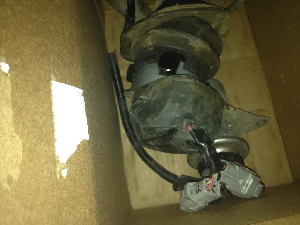
This is a pump from a sw20.
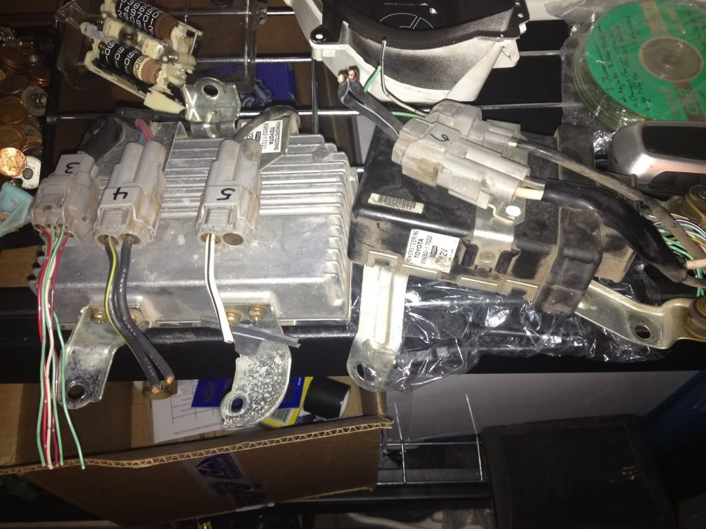
This the ecu for the sw20. I should note i have this setup for sale if any one in the U.S. what it.
The second type is full ellectric. Where the electric motor is attached to either the steering column or steering rack. While there are many different versions of these. I will only cover the 2004 and new toyota prius and 2006 toyota yaris. I will note that this conversion can be done completely using parts from a 2006 toyota yaris. The most important part is the EPS ecu needs to come from a yaris that does NOT have abs. The one quirk is that the ecu looks for both the rpm signal and wheel speed signal from the can network. The eps ecu will not provide assit tell it see the either one of these signal. I did look into reproducing the can signal but it would not be cost effective. This is where the NON ABS ecu provides a work around. The non abs ecu does not get its wheel speed signal from the can network. It get the signal from the instrument cluster in a standard 5v pulse. The only quirk with this is tell it see a pulse the ecu does not provide assit. Once it has see the speed signal it will continue to provide assit tell the ignition is cycled off. I did look it to building a small pulse generator and circuit has a work around but after driving the car with out the work around i found that it did not bother me enough to build the circuit. I find that when backing out of a parking stall the assit will start just after i need to start turning the wheel.
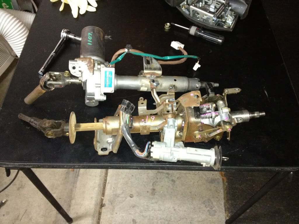 bottom is my stock steering column from a 1992 ae95 corolla alltrac wagon. The column is a tilt column.
The top is the EPS column from a 2004 toyota prius.
I started by disassembling my stock column.
 sorry my pic are not exact detail on tear down. But if you are attempt this conversion i would hope you would have the skills to figure out how the column comes apart.
 The 2004 prius column has two parts, the top tube is slide over the tube that is attched to the motor housing. The outter tube is crimped to keep it from sliding apart. I cut the crimped part with a die grinder and then was able to slide it off. The above pic is the column still together and i should note the upper tube has the factory mounting brackets attached to it.
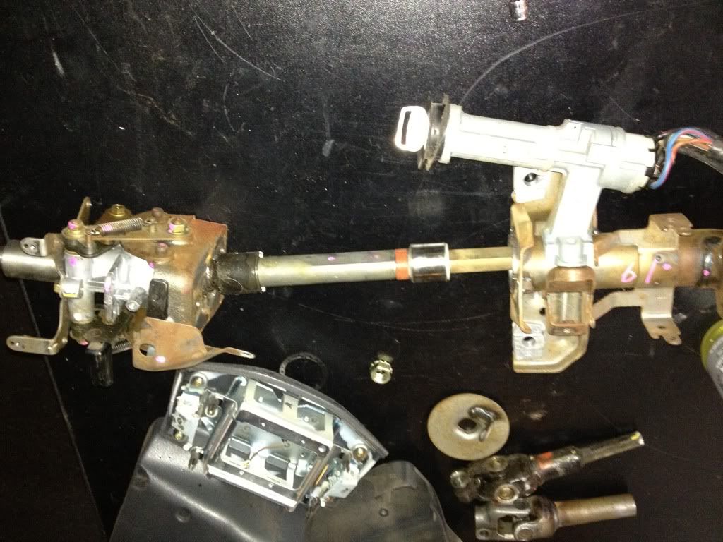
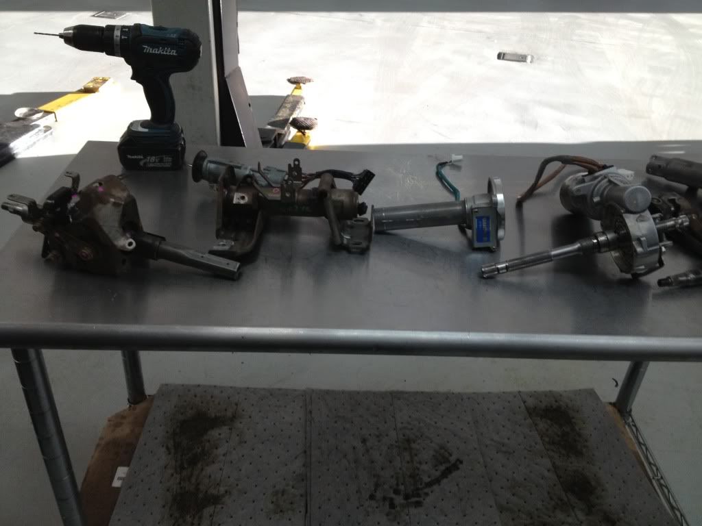
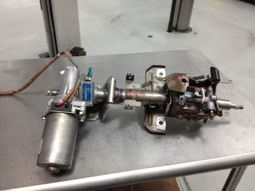
this pic is laying everthing out to work out how eveything will go together. The left part is the stock tilt mechanism, note the shaft sticking out. The next part is the main stock housing with the stock mounting brackets and ignition cylinder/switch. Then the prius part the first tube houses the torque sensor.(please take care to not damage this sensor.) the torque sensor is what to ecu uses to determine direction and amount of assit required. there is also a bearing in the housing. Next is the motor and gear housing. You will note this has a long shaft sticking out, this shaft hold the teeth that torque sensor looks for. On the other side is the output that will go the steering rack. The last part and not shown in the pic was the upper shaft from the prius, this shaft splines with the shaft coming out of the motor assembly. This shaft was measure ti figure out the length need, then the shaft coming off the original title mechanism. I had to finish removing the shaft from the mechanism. Once removed and measured out i cut the two shaft and wielded them together.
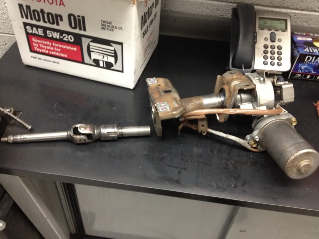 from the joint to the left is where the steering wheel mount. To the right of the joint first you will notice a collar with a notch. This notch is for the steering wheel lock when the key is out.
Necked is the housing which also was measued out cut and wielded together. But before it was wield i had to remove the torque sensor.
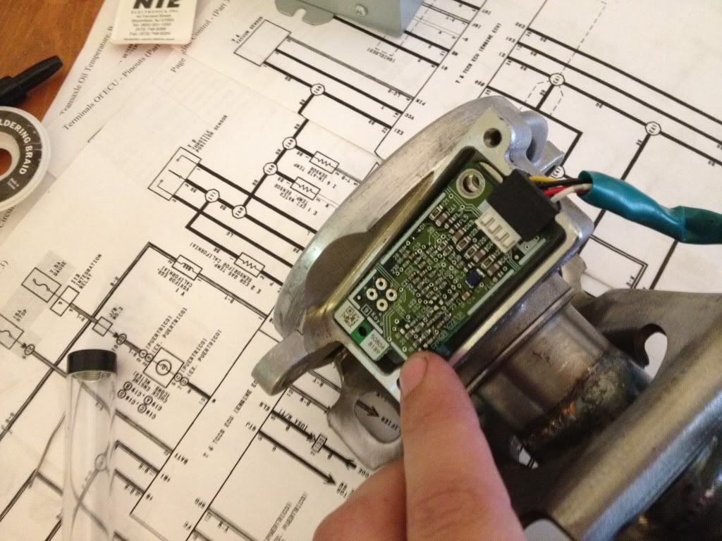 first i had to desoilder the circuit board. This is the four larger holes at the top of the circuit board above my finger.
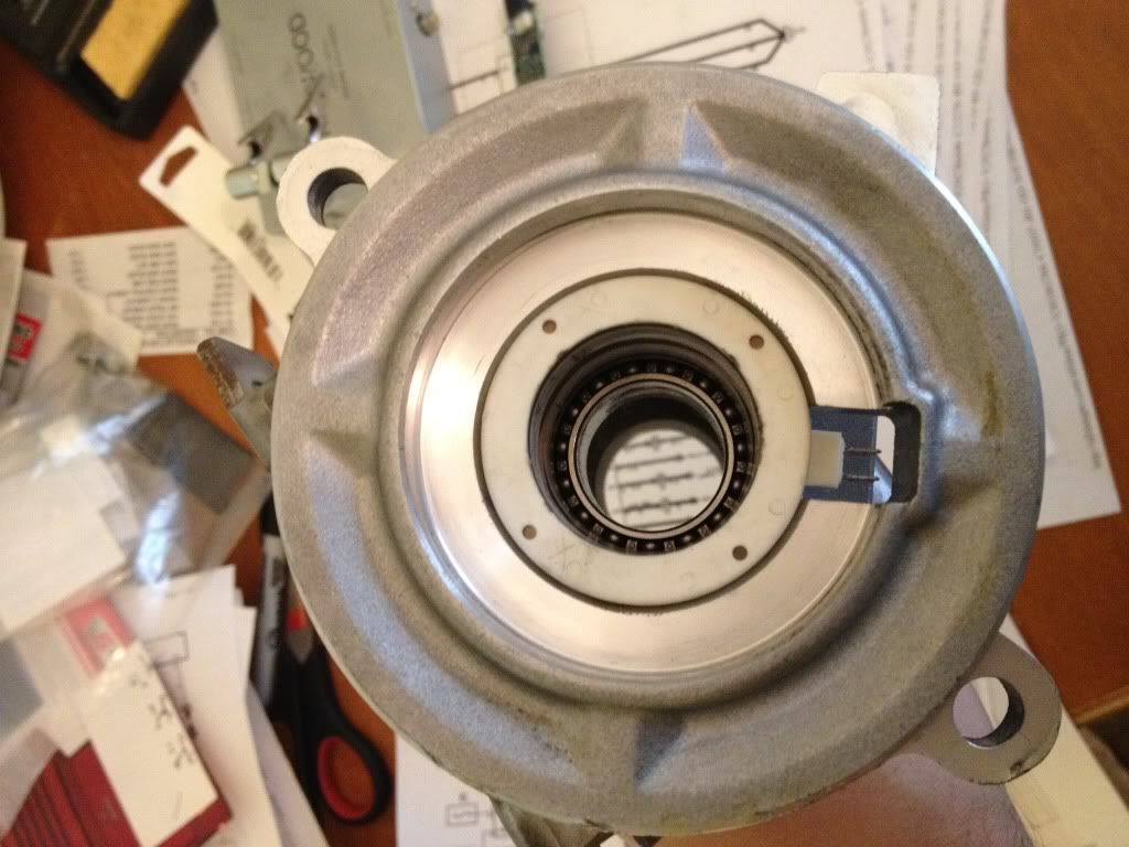 then carefully pulling the white cylinder plastic piece out. You can also see the bearing. This was left and seems to have servide the heat of wielding.
the housing all wielded up on the right side. I had to remove the lower mounting bracket and wield it back on with the EPS housing. Once wield i reinstalled the torque sensor and soilder the circuit board. Then install the upper shaft in the tilt mechanism and remounted the mechanism to the main housing.
All finished and ready to install in the car. I should note that make sure you test fit and measure to make sure the motor will not hit anything once installed.
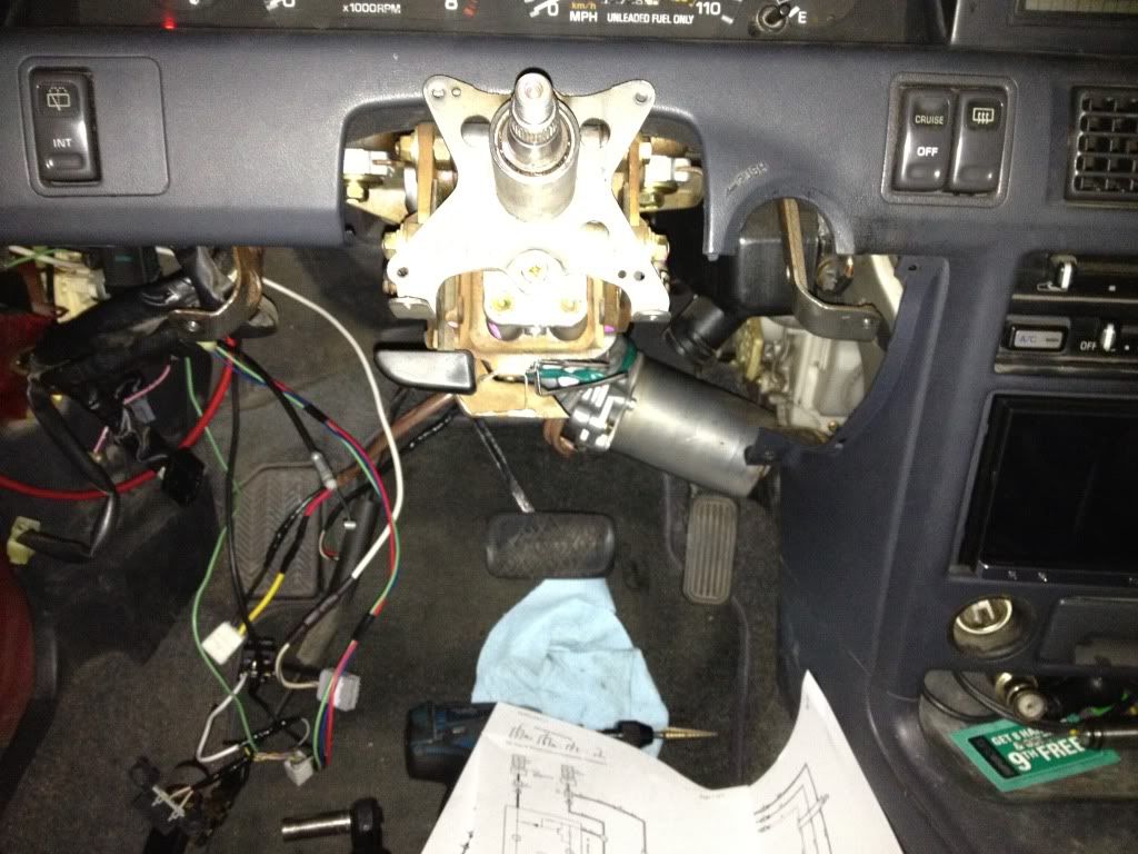
And here it is in the car.
Now that the easy part is done;) on to the hard part wiring. I should note that when you order your ecu make sure to get the wiring harness pig tails and connectors. With out them you may have a fun time locating the connectors (i have already tried order in the connector from toyota and while i had the part number toyota could not order them in) or end up soildering the wires striaght to the ecu.
First you will need to locate a location to mount the ecu, which will need to be close to be able to plug the harness from the column. I mount mine to the dash main brace to the right of the steering column. Sorry i did not take a pic of it mounted. Next will be building a high amp circuit. For this i used car audio amplifier power wire of 8awg, and a 50 amp fuse. The ecu has four connectors, one for the main power which is 2pins, a second for the motor also a 2pin connector. Then the torque sensor connector and last the main connector. The connectors for both the torque sensor and motor should just need to be plugged in. The high power two pin and main 12 pin connectors will need to be wired up. The high power will be the ground and 50 amp fused wire. Note the ecu has its own high amp relay so the 50 amp wire does not need to be switched. On the main 12pin connector will use only 4 pins, they will be pins 2, 5, 6 and 11. Pin 6 is the switched 12v power with 10amp fuse, this needs to be switch from the ignition switch. Pin 5 is the speed sensor signal wire. This need to be tapped to a 5v pulse generated signal. My ae92 corolla all-trac has a speed sensor built into the instrument cluster. I should note my car produces a 12v pulse but the eps ecu has fuctioned find despite the higher voltages. If your car does not produce a speed signal then a google search for a speed sensor adapter for aftermarket cruise control should work. The last 2 pins may or may not need to be used. If you bought both your ecu and column from the same vehicle then the torque sensor should still be calibrated and it should be plug and play, also some mix matching of columns and ecu may still function with out a problem. If not or if down the road there is a problem and the torque sensor need recalibrating, then these two pin will be need along with a dlc 3 connector. Pin 2 is the "SIL" this is the serial communication wire to go between the scan tool and the ecu. Pin 11 is the "TS" and this is the ecu diag pin. When this pin see ground then the ecu will communicate with the scan tool. The dlc3 connector is only needed if you need to connect a scan tool.
This is the EPS (electric power steering). First of there are two types of EPS i have encounter over the years. First is the style that use a electric hydraulic pump. These i have seen on sw20 2nd gen mr2 and mini coopers.
This is a pump from a sw20.
This the ecu for the sw20. I should note i have this setup for sale if any one in the U.S. what it.
The second type is full ellectric. Where the electric motor is attached to either the steering column or steering rack. While there are many different versions of these. I will only cover the 2004 and new toyota prius and 2006 toyota yaris. I will note that this conversion can be done completely using parts from a 2006 toyota yaris. The most important part is the EPS ecu needs to come from a yaris that does NOT have abs. The one quirk is that the ecu looks for both the rpm signal and wheel speed signal from the can network. The eps ecu will not provide assit tell it see the either one of these signal. I did look into reproducing the can signal but it would not be cost effective. This is where the NON ABS ecu provides a work around. The non abs ecu does not get its wheel speed signal from the can network. It get the signal from the instrument cluster in a standard 5v pulse. The only quirk with this is tell it see a pulse the ecu does not provide assit. Once it has see the speed signal it will continue to provide assit tell the ignition is cycled off. I did look it to building a small pulse generator and circuit has a work around but after driving the car with out the work around i found that it did not bother me enough to build the circuit. I find that when backing out of a parking stall the assit will start just after i need to start turning the wheel.
bottom is my stock steering column from a 1992 ae95 corolla alltrac wagon. The column is a tilt column. The top is the EPS column from a 2004 toyota prius.
I started by disassembling my stock column.
sorry my pic are not exact detail on tear down. But if you are attempt this conversion i would hope you would have the skills to figure out how the column comes apart.The 2004 prius column has two parts, the top tube is slide over the tube that is attched to the motor housing. The outter tube is crimped to keep it from sliding apart. I cut the crimped part with a die grinder and then was able to slide it off. The above pic is the column still together and i should note the upper tube has the factory mounting brackets attached to it.this pic is laying everthing out to work out how eveything will go together. The left part is the stock tilt mechanism, note the shaft sticking out. The next part is the main stock housing with the stock mounting brackets and ignition cylinder/switch. Then the prius part the first tube houses the torque sensor.(please take care to not damage this sensor.) the torque sensor is what to ecu uses to determine direction and amount of assit required. there is also a bearing in the housing. Next is the motor and gear housing. You will note this has a long shaft sticking out, this shaft hold the teeth that torque sensor looks for. On the other side is the output that will go the steering rack. The last part and not shown in the pic was the upper shaft from the prius, this shaft splines with the shaft coming out of the motor assembly. This shaft was measure ti figure out the length need, then the shaft coming off the original title mechanism. I had to finish removing the shaft from the mechanism. Once removed and measured out i cut the two shaft and wielded them together.from the joint to the left is where the steering wheel mount. To the right of the joint first you will notice a collar with a notch. This notch is for the steering wheel lock when the key is out.Necked is the housing which also was measued out cut and wielded together. But before it was wield i had to remove the torque sensor.
first i had to desoilder the circuit board. This is the four larger holes at the top of the circuit board above my finger. then carefully pulling the white cylinder plastic piece out. You can also see the bearing. This was left and seems to have servide the heat of wielding. the housing all wielded up on the right side. I had to remove the lower mounting bracket and wield it back on with the EPS housing. Once wield i reinstalled the torque sensor and soilder the circuit board. Then install the upper shaft in the tilt mechanism and remounted the mechanism to the main housing. All finished and ready to install in the car. I should note that make sure you test fit and measure to make sure the motor will not hit anything once installed.
And here it is in the car.
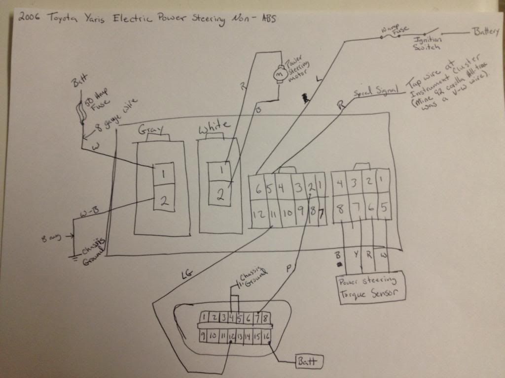
Now that the easy part is done;) on to the hard part wiring. I should note that when you order your ecu make sure to get the wiring harness pig tails and connectors. With out them you may have a fun time locating the connectors (i have already tried order in the connector from toyota and while i had the part number toyota could not order them in) or end up soildering the wires striaght to the ecu.
First you will need to locate a location to mount the ecu, which will need to be close to be able to plug the harness from the column. I mount mine to the dash main brace to the right of the steering column. Sorry i did not take a pic of it mounted. Next will be building a high amp circuit. For this i used car audio amplifier power wire of 8awg, and a 50 amp fuse. The ecu has four connectors, one for the main power which is 2pins, a second for the motor also a 2pin connector. Then the torque sensor connector and last the main connector. The connectors for both the torque sensor and motor should just need to be plugged in. The high power two pin and main 12 pin connectors will need to be wired up. The high power will be the ground and 50 amp fused wire. Note the ecu has its own high amp relay so the 50 amp wire does not need to be switched. On the main 12pin connector will use only 4 pins, they will be pins 2, 5, 6 and 11. Pin 6 is the switched 12v power with 10amp fuse, this needs to be switch from the ignition switch. Pin 5 is the speed sensor signal wire. This need to be tapped to a 5v pulse generated signal. My ae92 corolla all-trac has a speed sensor built into the instrument cluster. I should note my car produces a 12v pulse but the eps ecu has fuctioned find despite the higher voltages. If your car does not produce a speed signal then a google search for a speed sensor adapter for aftermarket cruise control should work. The last 2 pins may or may not need to be used. If you bought both your ecu and column from the same vehicle then the torque sensor should still be calibrated and it should be plug and play, also some mix matching of columns and ecu may still function with out a problem. If not or if down the road there is a problem and the torque sensor need recalibrating, then these two pin will be need along with a dlc 3 connector. Pin 2 is the "SIL" this is the serial communication wire to go between the scan tool and the ecu. Pin 11 is the "TS" and this is the ecu diag pin. When this pin see ground then the ecu will communicate with the scan tool. The dlc3 connector is only needed if you need to connect a scan tool.