20V Vacuum Hose Routing
Posted: Fri Aug 04, 2017 10:57 am
Hello C4AG!
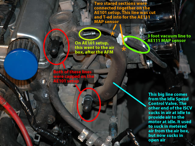
I may be beating a dead horse here but I've done some extensive research online and have piece-milled together whatever information I could find that makes sense. There is some contradicting information on the routes and a lot of forum threads are old with the pictures taken down. I feel this is a very important topic with swapping in a 20V and would be great to sticky and/or make this into a tech article. I need some assistance with identifying some routes with vacuum lines and the 20V. The motor is a ST with BT electronics.
Side-Notes:
- ST 20V with BT Electronics (MAP)
- Charcoal Canister will be used
- No A/C
- Power Steering will be used
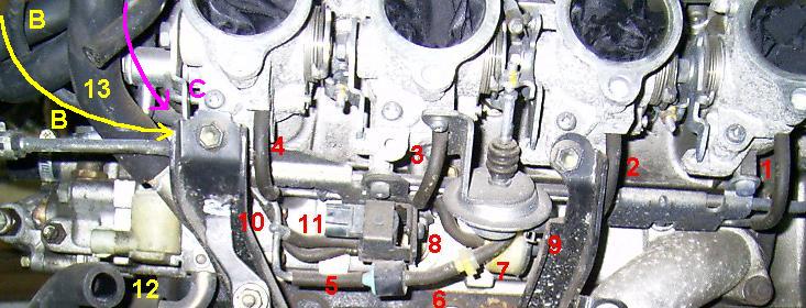
I have numbered each point in the pictures below and wrote a brief description of what I think is supposed to be connected at that point. If you could help me verify what is correct and identify the points of question, I would really appreciate it!


1.) Throttle 1 – Vacuum Equalizer
2.) Throttle 2 – Vacuum Equalizer
3.) Throttle 3 – Vacuum Equalizer
4.) Throttle 4 – Vacuum Equalizer
5.) Fuel return line entrance (From Regulator)
6.) Fuel return line exit (To fuel tank)
7.) Central point exit for all 4 throttle vacuum equalizers (To MAP Sensor)
8.) Exit to MAP Sensor via 1 way valve
9.) Exit from Throttle Opener
10.) Exit to point 11 through manifold via 1 way valve.
11.) Where does this exit to?? VSV?
12.) Exit from VSV to Point 13 through manifold?
13.) Where does this exit to? Capped?
14.) Exit from VSV to Point 16 through manifold?
15.) Where does this enter from? Capped?
16.) Charcoal Canister
17.) ISCV Input
18.) What is this?
19.) Pressurized output to power steering idle-up valve (Not used)
I may be beating a dead horse here but I've done some extensive research online and have piece-milled together whatever information I could find that makes sense. There is some contradicting information on the routes and a lot of forum threads are old with the pictures taken down. I feel this is a very important topic with swapping in a 20V and would be great to sticky and/or make this into a tech article. I need some assistance with identifying some routes with vacuum lines and the 20V. The motor is a ST with BT electronics.
Side-Notes:
- ST 20V with BT Electronics (MAP)
- Charcoal Canister will be used
- No A/C
- Power Steering will be used
I have numbered each point in the pictures below and wrote a brief description of what I think is supposed to be connected at that point. If you could help me verify what is correct and identify the points of question, I would really appreciate it!
1.) Throttle 1 – Vacuum Equalizer
2.) Throttle 2 – Vacuum Equalizer
3.) Throttle 3 – Vacuum Equalizer
4.) Throttle 4 – Vacuum Equalizer
5.) Fuel return line entrance (From Regulator)
6.) Fuel return line exit (To fuel tank)
7.) Central point exit for all 4 throttle vacuum equalizers (To MAP Sensor)
8.) Exit to MAP Sensor via 1 way valve
9.) Exit from Throttle Opener
10.) Exit to point 11 through manifold via 1 way valve.
11.) Where does this exit to?? VSV?
12.) Exit from VSV to Point 13 through manifold?
13.) Where does this exit to? Capped?
14.) Exit from VSV to Point 16 through manifold?
15.) Where does this enter from? Capped?
16.) Charcoal Canister
17.) ISCV Input
18.) What is this?
19.) Pressurized output to power steering idle-up valve (Not used)