4A-G Crankshaft, Front Pulley & Flywheel
Complied and written by Richard White, submitted 1/05
4A-G Crank
The 4A-G crank is by all appearance a high performance piece of hardware. Unlike many production crankshafts which are nodular cast iron, the 4A-G is forged. It is a forged carbon steel, five main bearing, fully counter balanced affair. Each journal is cross drilled for 360-degree supply of oil to the connecting rod bearings, and each hole is chamfered to aid in oil delivery. An additional feature of the 4A-G crank is that each main bearing journal has rolled fillets to improve fatigue strength.
The transition between the main bearing surface and the crank counter weight and rod journal is subjected to very high torsion forces. Compressing the material around the transition, increases the strength and, therefore, the life of the crank. Other performance features include the use of a roller bearing (Toyota p/n 90363-12003) for the transmission pilot shaft (T50 Transmission only) and the use of eight 10mm fly-wheel bolts rather than the usual six that many engines of this size would normally have. This is contrary to Toyota’s illustrations in their own repair manuals typically showing six. And because there are no dowel pins to locate the flywheel position Toyota uses close fitting shoulder bolts. If the flywheel and crankshaft are fitted and torqued properly, all the stress (compression/friction) should be at the interface between the crankshaft and flywheel and the bolt’s shear strength is only needed if something in the system has failed. Rarely do you want a design that uses a fastener in a single shear plane. Bolts are at their best in tension.
The eight fly wheel bolts add considerably to the strength of the assembly and the roller bearing pilot bearing reduces parasitic frictional losses between the input shaft of the transmission (T50) and the crank. It also aids in keeping the mis-alignment between the transmission and engine to a minimum while supporting the end of the transmission input shaft, reducing the likelihood of bending it. However, it is curious that the crankshafts for front wheel drive transmissions (transverse mounted configurations) do not have a pilot bearing, even though the crank shaft has a machined pocket for it.

For those interested in additional strength and durability, ARP (pictured on the bottom) offers a replacement for the Toyota 4A-G fly wheel bolts. It is a 10mm x 1.25 bolt, 12 point (half inch head); rated at 190ksi tensile strength, part number 203-2802. The ARP bolts are torqued to 58ft-lbs. (with ARP Moly Assy. Lube)(85ft-lbs. with 30wt motor oil) as compared to the stock 54ft-lbs. Before using the ARP bolt it is necessary to verify that the fly wheel holes have adequate chamfer to clear the radius under the head of each bolt. The threads should also be clean and the hole free from debris.
Even though all 4A-G crankshafts have the same high strength features, there are two variations. The early model has the small rod journal diameters (40mm)(p/n: 13401-16010) and the later models have the large rod journals (42mm)( p/n: 13401-16020). And other than that, they are indistinguishable.
It is interesting to note that all the late model, large crank pin cranks-shafts are identical, i.e., same Toyota part numbers. However in reviewing the maintenance manuals, Toyota calls out much tighter inspection tolerances in the last generation 20 valve. The obvious reason would be to keep parasitic friction and vibrations to a minimum due to the difference in max engine speed that the 20 valve engines were allowed to turn versus the 16 valve ones.
The 20 valve engine manual specifies that the crank be straight to 0.03mm. Each main journal should be within 47.982~48.010mm (1.8891~1.8898inch) diameter, taper and out of round to within 0.005mm (0.0002inch), and run out to within 0.03mm (0.0012inch) max. By comparison, the tolerances specified in the other Toyota manuals for the late model 16 valve engines are larger. Each main journal should be within 47.982~48.010mm (1.8891~1.8898inch) diameter, taper and out of round to within 0.02mm (0.0008inch), and run out to within 0.06mm (0.0024inch) max.
As an additional note, TRD specifies its Group A and N2 crankshafts have a crankshaft “bend” of less than 0.01mm.
When rebuilding the engine, the crank, like the block, should be thoroughly cleaned and inspected. Each throw phased checked. It should be flat, 180 degrees. And each bearing journal should not only be visually inspected but felt with the finger nail for any ‘grooves’ or deep scratches. There should be none.
During disassembly, one should (must) keep all the matching parts together and labeled, identifying its location. The same goes for the used bearings. By keeping the old bearings together with its bearing cap one can inspect and note the OEM Bearing size number printed on the back side for easier replacement. However, if one of the numbered markings can not be determine, the correct bearing can be selected by adding together the numbers imprinted on the cylinder block and crankshaft, then select the bearing with the same number as the total. There are 5 sizes of standard bearings, marked 1, 2, 3, 4, and 5. Please note, the small journal cranks had the bearing size stamped only on the block.
|
|
Stamped Number Mark |
||||||||
|
Cylinder Block # |
1 |
2 |
3 |
||||||
|
Crankshaft # |
0 |
1 |
2 |
0 |
1 |
2 |
0 |
1 |
2 |
|
Select Bearing # |
1 |
2 |
3 |
2 |
3 |
4 |
3 |
4 |
5 |
As an example (see colored in blue) if the stamped number in the first position on the block is a 2 and the stamped number in the second position on the crank is a 2 you would select a #4 bearing for the number 2 main.
After cleaning the crankshaft, the crank should be crack tested. A crankshaft destined for severe duty must be free of flaws. After Magnaflux crack testing, the crank should be fully de-magnetized, as any residual magnetism after Magnaflux testing will attract ferrous metal particles to the area, which would soon wipe out a bearing.
A quick method to check the crank can be done with the crank mounted on top of the main bearing caps, e.g., the crank sitting on the main bearing saddles. With a cleaned crankshaft and main bearings, the crank can be checked for straightness by first re-installing the crank and all the bearing shells in the block. All bearing surfaces must be coated with light machine oil. The main bolts (or studs if up graded) should also be lubricated and torqued to specification. If the crank turns freely by hand (very little effort), it is straight enough for heavy-duty use.
A more through inspection would require the crank be checked on a lathe and spun to ensure that the pilot bearing is concentric with the centerline of the crank, and the flywheel mounting flange is perpendicular to the crank centerline. A large variance in either area is rare, but if it exists, it is nearly impossible to correct. An out of center pilot bearing and/or a non perpendicular flywheel mounting flange would cause large uncorrectable imbalances and is abusive to the clutch.
An often over looked inspection is that of End play or Thrust clearance. Toyota specifies it to be between 0.020~0.220mm (0.0008 ~ 0.0087inch). Moreover, it is recommended that you check endplay before final assembly of the engine, after it is assembled and after the engine is bolted to the transmission. It is important to verify that the input shaft of the transmission is not bottoming out against the crankshaft, thus eliminating endplay in the engine, resulting in premature wear in the thrust bearings and causing an endless amount of speculation about the cause.
It is important that all the checking and inspection of the crank be done early in the inspection and pre-assembly re-building process. Gathering and using this information will allow one to build a high performance 4A-G engine and most importantly insure its longevity. It makes no sense to spend a lot of money preparing the crank only to learn that you can not use it because it was cooked, bent, damaged, etc.
Though many engine builders find little modification is needed with a 4A-G crankshaft that will be used in a high performance application, there are several recommendations that have been made. With the journals protected with several layers of duct tape, all burrs should be removed and the crank polished. This includes the journals too. This eliminates stress risers that could lead to failure of the crank. The duct tape is inexpensive and protects the bearing surfaces against nicks in a journal while grinding.
Toyota quality control is quite good as you will rarely see burrs around the oiling holes. However the oil holes should be brushed clean with a 22~25 caliber brush (0.22 ~ 0.25inch dia).
Please note, it is ideal to remove the oil plugs that have been pressed and staked in place to block off the cross-drilled oil way and replace them with a threaded plug. However a word of warning, the ball bearing type plug and crank are extremely hard and grinding or milling will be necessary to remove them for a thorough cleaning of the oil way that would otherwise not be possible, i.e., accessible. Also, care should be exercised in tapping the threads into the crankshaft. The opening to the oil hole is not usually square or perpendicular to the surface and it is quite easy to mis-guide the tap and possibly break it. A circumstance you should avoid.
Lightening the crank can be beneficial in removing mass and lowing inertia for better engine response and reducing bearing loads. Cleaning up the counter weights smoothes the surface and reduces the total “wetted” surface area where oil will cling. The resulting effect reduces the rotating weight and puts the oil back in the sump where it belongs. However, the amount of weight removed from the crankshaft should be planned for, and balanced with the weight of the rods and pistons (and other assorted fasteners, e.g., pin, rings, bolts, etc.)
The term “knife edging” of the counterweights refers to reducing the mass of the counter weight on an angle rather than keeping a straight cut. The idea is to reduce weight, lower the inertia and reduce aerodynamic drag as the crank tries to move/rotate through the crankcase atmosphere, enabling the crank to speed up more quickly. There is little aerodynamic benefit with “knife edging” a crank that will be used in a dry sump system. A good dry sump system pulls a vacuum in the crankcase. With such a system, the counter weights would have less opportunity to impact the thick oil vapor environment when it is spinning. Never the less, reducing the crank’s mass and reducing the ‘wetted’ surface area is always a benefit of a high performance crankshaft.
To assist in the smooth operation of the motor and to reduce bearing wear, the crankshaft should be dynamically balanced. This will reduce harmonic loading and vibration that any imbalance would cause. However because of the physical nature of the four stroke, inline four-cylinder configuration, ultimate balancing can not be achieved to the next, or second harmonic order, like a 60 degree V12, inline 6 or a boxer four. Moreover, unless one has access to a machine that electronically balances the crankshaft, assistance should be sought to properly balance the crank along with the intended components that will be used on the engine, e.g., front pulley, rods, pistons, rings, Fly Wheel and fasteners. TRD recommend the crankshaft and flywheel both be balanced separately and together to a balance torque of less than 10g-cm.
There are a couple of different techniques that have been used in balancing crankshafts. Typically, material is drilled out of the circumference of the crank’s counter weight. Another way would be to angle cut (like knife edging) the edges of the counter weights. This technique is much more difficult and time consuming.
Adding weight can be done by adding (pressing) heavy metal into a similar drilled hole. However, this is not recommended, since at high speeds the centripetal forces could pull the plug out. It is recommended to press the heavy metal plug into the side of the crank’s counter weight. Another nice, but expensive balancing technique is to weld over the “lightening” holes and grind/polish them flush with the surface. This keeps the “wetted” surface area down, keeping oil clinging to the crank to a minimum and allows for better aerodynamics.
The last operation done to the crank should be to micro polish the main and rod journals. Small scratches in the journal will cut into the bearing and shorten its life. A polished surface insures maximum ‘rubbing’ area while minimizing any cutting action a rough surface would have. Another benefit is the elimination of a possible stress site where a crack could start and destroy the crank.
One thing that is not recommended for an OEM 4A-G crankshaft is the application of any form of heat treating. Heat treating could change the attributes that Toyota has designed into their crank.
But as an interesting side note, most production cranks destined for performance work are heat treated. The common form of heat treating is Tufftriding. Contrary to popular opinion, it does not increase the core strength of the crank. The Tuftride bath, composed primarily of cyanide and cyanate compounds, that releases specific quantities of carbon and nitrogen in the presence of ferrous materials such as cast iron and alloy steel. Nitrogen is more soluble than carbon in these metals and diffuses into the surface on the crank, while the carbon forms iron carbide particle at or near the surface. These particles act as nuclei, precipitating some of the diffused nitrogen to form a tough compound zone of carbon-bearing epsilon iron nitride.
At the surface is a compound zone (0.0003 ~ 0.0005” deep) that is tough and very resistant to wear, galling, seizing and corrosion. Below the surface (0.0008 ~ 0.0014”) is an underlying nitrogen diffusion zone. This zone is responsible for improved fatigue properties. The nitrogen, in solid solution, prevents incipient cracks from becoming fatigue failures.
In any case it is not recommended to Nitride, Tuffride, or perform other heat treatments to the OEM crank. The strength of the rolled fillets will be lost and the possibility of warping the crank is a risk that would result in an additional straightening process.
A word of warning, if the crank is to be stored for any length of time outside the engine, the crank is easily susceptible to corrosion, i.e., rust, and must be protected from moisture. The author has found a marine product, Boeshield, to be an improvement over other similar produces like WD-40. However, the use of WD-40 or any other corrosion inhibiting coating is superior to using none at all. The idea is to keep moisture and air away from the crankshaft surface.
For those interested in using or stroking the 4A-G crank a word of caution is in order. The 4A-G block is only capable of accepting something less than 83mm (stroke) and at that, requires grinding on the inside of the block, at the bottom of the cylinders to obtain the necessary clearances between the block and the shoulders of the connecting rod and/or connecting rod bolts.
An old hot rodder’s trick was (is) to “weld up” the crank throws and re-grind the connecting rod journals. This process is highly dependent on the skill of the welder to eliminate any inclusions or voids in the welding and the machinist to index and properly grind the journal with the proper fillet radii and run-out measurements. For a moderate increase in street performance this may be acceptable, but for an all out competition engine, it would not. The weld material and crank will inevitably not have the same molecular make up, resulting in a different grain structure, i.e., grain boundaries. These molecular structures will not be in alignment. Even though you can not see the grain boundaries with the naked eye, they can be viewed with a micro-scope if the crank was cross sectioned and the welded area polished and stained. Moreover, grain boundaries create weak areas in the metallurgy where stress concentrations will form and if the crank is strained beyond its capabilities, will (could) fail from fatigue.
The only acceptable standard for a competition engine is a crank machined from a forged billet. These are the most expensive and strongest cranks available. They are fully machined from a hammer forged bar (billet) of high-grade steel, heat treated and polished to further enhance its strength and fatigue resistance. These cranks have the ability to endure repeated high bending and twisting loads. Attention to the these expensive details are very important to any high rpm race engines. Like the 4AG crank, high rpm/endurance race cranks are generally fully counter balanced at each pin. This shortens the torsional loads on the crankshaft by distributing the mass along the crank. The one used in the 4A-G Formula Atlantic engine is TRD crankshaft, part number 13401-FT001.
For inspection purposes, the following tables have been included. The first table lists the dimensions for the crankshaft main journal, the main bearing bore diameter and the crank pin diameter as they correspond to the factories inspection stampings on the crank. The second table compares dimensional clearances between the different types of cranks and notes the approximate weight for each crank. The third and forth tables lists the standard wall thickness of the OEM and TRD bearings. And the last two tables reference TRD’s (large pin and small pin crankshafts) Group A and N2 main bearing bore, crank journal diameter and pin diameter requirements.
|
OEM Toyota |
Stampings on Block or Crank |
Dimension |
|
Inside diameter of cylinder block main bearing bore |
1 2 3 |
52.025~52.031mm (2.0482~2.0485inch) 52.031~52.037mm (2.0485~2.0487inch) 52.037~52.043mm (2.0487~2.0489inch) |
|
Crankshaft journal diameter |
0 1 2 |
47.994~48.000mm (1.8895~1.8898inch) 47.988~48.994mm (1.8893~1.8895inch) 47.982~48.988mm (1.8891~1.8893inch) |
|
Crank Pin Diameter, Small, 4A-GEC, 4A-GECU, p/n 13401-16010 |
na |
39.985 ~ 40.00mm (1.5742 ~ 1.5748inch) |
|
Crank Pin Diameter, Large, 4A-GE, 4A-GZ, 20V, p/n 13401-16020 |
na |
41.985~42.000mm (1.6530~1.6535inch) |
Even though the above table was referenced from Toyota’s own engine repair manuals, most high performance engine builders prefer not to assume or take a chance that the markings on anything would be correct. They will (should) take the time to measure each and every component and figure out the required clearances.
Oil Clearance and Crank Comparison
|
Crank Type |
Main Bearing Clearance |
Thrust Bearing Clearance |
Weight |
|
TRD F/A p/n:13401-FT001-A |
0.0020 ~ 0.0028inch |
0.003 ~ 0.006 inch |
Min. 28 lbs. |
|
TRD AE86 & AE82 Group A, N2 p/n: 13401-AE801 |
0.050 ~ 0.065mm |
NA |
|
|
TRD AE92 Group A p/n: 13401-AE902 |
0.055 ~ 0.070mm |
NA |
|
|
20V p/n: 13401-16020
|
Std. 0.015 ~ 0.045mm (0.0006 ~ 0.0018inch) |
Std. 0.020 ~ 0.220mm (0.0008 ~ 0.0087inch) |
12.695kg* (27.99Lbs.) |
|
89 MR2, 91’ Hi Comp, 4A-GZ, etc. large crank pin p/n: 13401-16020 |
Std. 0.015 ~ 0.033mm (0.0006 ~ 0.0013inch.) |
Std. 0.020 ~ 0.220mm (.0008 ~ .0087inch) |
|
|
16V, early AE86 and AW11, small crank pin, p/n 13401-16010 |
Std. 0.012 ~ 0.049mm (0.0005 ~ 0.0019inch) |
Std. 0.020 ~ 0.220mm (0.0008 ~ 0.0087inch) |
11.660kg* (25.70Lbs.) |
* Weight was measured on a single sample.
Please note the TRD Formula Atlantic (F/A) crankshaft is supported by a dry sump lubrication system, and it is not necessary to have “flats” machined into the nose of the crank to drive the “normal” oil pump mounted on the front of the engine. The weight of a Formula Atlantic crank is governed by CART Toyota Atlantic rules. And each builder is allowed to “lighten” the crank by keeping the mass of the crank close to the mains. This weight reduction is done to the counter balances and pins so long as the identifying marks are not removed and the weight is above the minimum allowable.
The crank pin diameter for Toyota’s Large journal crank should be within 41.985~42.000mm (1.6530~1.6535inch). The crank pin diameter for the Small journal crank should be 39.985~40.000mm (1.5742~1.5748inch).
Toyota OEM Crankshaft bearings:
|
Part number (PNC 11711-): |
Stampings mark # |
Center thickness of bearing |
|
Std. Size bearing 11701-15050-01 (-16010-01) 11701-15050-02 (-16010-02) 11701-15050-03 (-16010-03) 11701-15050-04 (-16010-04) 11701-15050-05 (-16010-05) |
1 2 3 4 5 |
2.002~2.005mm (0.0788~0.0789inch) 2.005~2.008mm (0.0789~0.0791inch) 2.008~2.011mm (0.0791~0.0792inch) 2.011~2.014mm (0.0792~0.0793inch) 2.014~2.017mm (0.0793~0.0794inch) |
TRD Group A, N2 Crankshaft bearings:
|
Part number* |
Center thickness of bearing (mm) |
|
|
11701-AE801-01 |
2.0 |
-0.004 -0.008 |
|
11701-AE801-02 |
2.0 |
+0.0 -0.008 |
|
11701-AE801-03 |
2.0 |
+0.004 -0.0 |
|
11701-AE801-04 |
2.0 |
+0.008 +0.004 |
* Bearing Set is 5qty.
Using a cylinder bore gauge, the oil clearance of the combined bearing thickness, crank journal diameter and the block’s main bearing bores should be 0.050 ~ 0.065mm(Small journal TRD Group A, N2), 0.055 ~ 0.070mm(Large journal TRD AE92 Group A),.
TRD’s Crank Shaft Requirements *
|
|
TRD AE86 & AE82 Group A, N2 p/n: 13401-AE801 |
Dimension (mm) |
|||
|
Inside diameter of cylinder block main bearing bore |
52 |
+0.050 +0.020 |
|
||
|
Crankshaft journal diameter |
48 |
+0.0 -0.015 |
|
||
|
Crank Pin Diameter |
40 |
+0.0 -0.015 |
|
||
|
TRD AE92 Group A p/n: 13401-AE902 |
Dimension (mm) |
|
|
|
Inside diameter of cylinder block main bearing bore |
52 |
+0.050 +0.020 |
|
|
Crankshaft journal diameter |
48 |
+0.0 -0.015 |
|
|
Crank Pin Diameter |
42 |
+0.0 -0.015 |
|
* Crankshaft bend <0.01mm
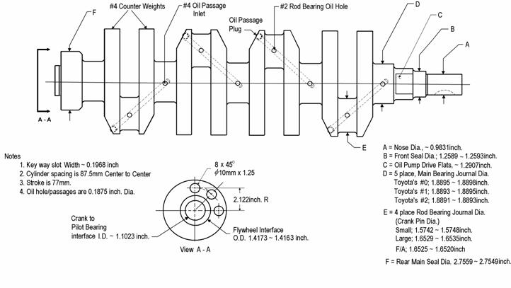
The above sketch of the 4A-G crankshaft shows the oil passage, where oil travels from the main bearing journal to the crank pin. Please note that drilling the oil passage openings across the journal in this manner keeps the maximum amount of material (max strength) in the cross section that is subject to highest level of forces in shear.
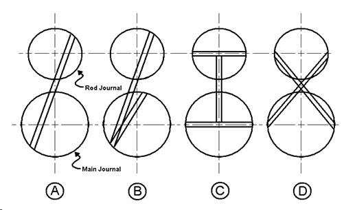
The above illustrations depicts the cross sectional, head on view, of various crankshafts. There are several oiling strategies that have been used to move oil from the main journal to the rod journal. ‘B’ – represents how the 7A crankshaft or the new 2ZZ transfers oil to the rod journal. However there is only one opening in the rod journal and the main journal oil holes are off set from the center of the crankshaft. This does not allow a constant 360 degree flow of oil. ‘C’ – models the 4A-G crank. Oil is available to the other side of the main journal and both sides of the rod journal.
16v AE86 Crank:

This photo is a small rod journal, 40mm, example. Notice that it is fully counter balanced.

This photo of the small rod journal crankshaft shows the rolled fillets of the main bearing journal and the cross drilling of the oil passages. Notice that the oil outlet / inlets are located in the center of the journal.
![]()
![]()
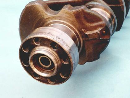
Notice the eight hole bolt pattern that is typical of all 4A-G cranks, and the pilot bearing pocket (a) for the T50 transmission. Also notice the ‘ball bearing’ type plug (b) that closes off the end where the oil passage was created during the manufacturing process.
20v AE101 Carnk:

The above photo is a crank from an AE101 20valve engine. It is identical to the other large, 42mm crank pin, 4A-G crank shafts.

This is a close up view of the large journal crank. Notice the rolled fillets on the main journal and the number stamped on the counter weights. Those numbers represent the bearing and journal size needed during assembly. The earlier cranks where not marked on the crank but where marked on the block.
Stroker 16V small journal crank:
This photo is of a ‘stroked’ small journal 4A-G crank shaft. Notice the welds on top of the rod journals and the resulting offset crank pin oil holes. It is hoped that the quality put into this crank will be adequate for street use, as the quality of the welds can only be inspected by x-ray.
![]()
![]()


a - Close up view of the welding required to build up a “stroker” crankshaft rod journal. b – Typical resulting void discovered during the re-grinding of the rod journal. Wrong filler rod, i.e., less than idea material compatibility, voids, inclusions and thermal stress could lead to a weaken area if not done correctly.
7A Crank:

This is a photo of a 7A crankshaft. Its stroke is 85.5 mm and weights 32.5 Lbs. Though it is forged vanadium steel and fully counter balanced, there are features about this crank that one should be aware of that make it less than ideal for heavy duty competition. Please note that this crankshaft can not fit into a 4A block. The crankshaft pin diameter is 48.0mm. The counter weight outside diameter is 69.0mm, and the counter weight “arm” thickness is16.75mm. This makes the journal and counter weights too large and the resulting connecting rod angle too great for one to fit it in a 4A-G block.

This picture of the 7A crankshaft shows the location of the oil passages. The holes/passages are all on the same plane. This makes it easier for manufacturing since the crank does not have to be rotated or the drilling machines indexed 90 degrees. Also notice this design does not require plugging. However the placement of the oil holes and passages takes away needed material from a critical area and compromises the cranks ability to combat the larges forces being applied in shear on the journals and mains.

This photo shows the unique fillet rolling on both the crank main and rod journal fillets on the 7A crank. This practice is to increase strength at the area that is subjected to the highest stresses. Also notice the off center oil hole of the main bearing journal. This position will not allow a full 360 degree supply of oil to the rod journal. And it is positioned in a less than ideal area to take advantage of the maximum width and maximum strength of the journal.

This photo of the 7A crankshaft shows the less expensive manufacturing process of only drilling and tapping six holes for the flywheel. Eight is the minimum needed for heavy duty usage. However there is ample room to add a couple of shear pins.

This is a photo of an experimental light weight, 23.5lbs. Toysport 4A-G crankshaft. Notice the larger counter weights have been ground away leaving these rather larger “shoulders” around the main bearing journals.

This is a close up view of the 5/16” - 18 socket set screw oil plug about to be put into the newly tapped oil passage way. Again notice the large amount of material removed from the counter balance. Use of this type of crank would require very light weight pistons and rods to help in balancing the complete assembly.
4A-G Front Pulley
One of the last items that is reviewed by the engine builder and often over looked as a performance item is the crank pulley. All ‘stock’ OEM 4A-G front pulleys have a cast iron hub and the pulleys are machined for the reinforced, five rib, flat rubber drive belts. It appears that early 4A-G engines (AE86) have isolated the inner pulley (pulley closest to the engine) by a thin layer of black rubber (elastomer) while the outer pulley is a contiguous part of the hub. An exception to this is the 4A-GZ, supercharged pulley and the black top 20v pulley. On these, both the inner and outer pulleys are isolated from the center hub. The layer of black rubber is relatively thin (aprox. 3 mm).
Because Toyota balances their engines fairly well, this researcher would rather not categorize the 4A-G pulley as a harmonic balancer. The typical harmonic balancer is constructed such that it has a mechanical means to dampen the rotating, torsional, imbalances caused from loose (poor) manufacturing practices and materials used for the crankshaft, pistons and flywheel. Typical harmonic balancers are hollow inside, either filled with a heavy silicone like substance, used to counter imbalances, or have some other kind of heavy mass. The heavy mass is some times called an inertia ring. This inertia ring is separated by a thin rubber buffer that isolates and absorbs the crankshaft’s natural frequencies and their harmonics. It is a simple rule of physics that states that if the crank stays at its natural resonant frequency (at RPM), those vibrations (harmonics) will add to the destructive forces to eventually break the crankshaft.
The 4A-G pulley appears to be designed to absorb high frequency vibration caused from the optional power steering pump and/or air conditioner when they are turned on, or (though it’s hard to imagine) to isolate these accessories from the engine. The GZ and late model 20v attempted to isolate the crank from all accessories. In both models of pulleys, it is the inside and outside pulley that are isolated from the crank, and in all cases the mark for the ignition reference is not considered a “hard” reference since the rubber isolator could allow the outer rim of the pulley to move or slip from its position.
As a point of reference, the 4A-GZ supercharged inner pulley drives the water pump and super charger. While the outer pulley drives the optional power steering pump, alternator and air conditioner. With all other models, the inner pulley drives the water pump and alternator and the outer pulley drives the optional power steering pump and air conditioner.
As noted earlier, the 4A-GZ pulley not only isolates those accessories but also isolates the alternator and supercharger as well. Because there is a layer of rubber between the inner pulley and the hub, one should verify the pulley is bonded to the hub and the rubber is not deteriorating. It is also important to inspect the alignment between the pulley and the accessories.
Among the various engine/chassis applications, there are noted differences between 4A-G pulley models. The differences are the pulley diameters, position of the outside pulley (pulley furthest from the engine) and the location of the timing mark. Therefore, one should always take note and verify the timing marks against top dead center of the number one piston.
Even though it is common practice to pre-assemble an engine destine for performance duty, it is also necessary to verify the location of the timing mark and belt alignment prior to final assembly and engine installation into the vehicle. It is becoming common to discover used 4A-G engines to not have their original pulleys. Because of the uncertainty of using the correct pulley and the design (heavy and vague timing mark) of the OEM pulley, many engines destined for severe duty do not use stock pulleys. TRD has listed a pulley with degree graduations marked on the edge, part number 13471-AE801. Need less to say, the use of a purpose build performance oriented pulley usually means giving up the comfort of power steering and air conditioning.
For a more positive and efficient way to power accessories, TRD, like other racing engine builders has offered tooth pulleys to drive the external oil and water pumps, [Crank pulley part number 15152-FT001 (16 tooth), oil pump pulley part number 15102-FT001 (32 tooth) or for the N2; 15152-AE801 (17 tooth), 15163-KP611 (27 tooth) and water pump pulley 16371-AE801, alternator pulley 27411-AE801] [Crank pulley, water pump drive part number 16374-FT001 (20 tooth) and water pump pulley part number 16371-FT001 (30 tooth)].
The Formula Atlantic motor also has optional gear ratio pulleys available for the water and oil pump pulley cluster, e.g., part numbers 13521-FT002 and 13521-FT001. The draw back of using a cogged belt is the noise and cost. On the other hand, the draw back of using the stock, OEM, 5 rib drive belt is the unfortunate creation of friction and added side loads on the accessories’ bearings. These belts require a specific amount of tension that ultimately results in friction, which is the performance tuner’s enemy. One should consult the Toyota engine maintenance manual for the proper tension.
Toyota’s Recommended Belt Tension with tension gauge
|
|
Water Pump |
PS and/or AC |
Alternator & AC |
Alternator with out AC |
With out PS |
|
AE92 w/ 4A-G |
115 lbs |
90 lbs |
------ |
------ |
------ |
|
AW11, MR2 |
115 lbs |
105 lbs |
------ |
------ |
----- |
|
AW11 4A-GZ |
115 lbs |
------ |
85 lbs |
115 lbs |
----- |
|
AE86, 4A-GE |
115 lbs |
115 lbs |
------ |
------ |
130 lbs |
|
AW11, 1989 |
115 lbs |
115 lbs |
------ |
------ |
------ |
|
AE111, “Black Top” |
30 ~ 45 kg |
----- |
------ |
------ |
------ |
|
AE101, 4A-GZ |
30 ~ 45 kg |
----- |
37 ~ 55 kg |
30 ~ 45 kg |
30 ~ 45 kg |
|
AE101, “Silver Top” |
25 ~ 40 kg |
30 ~ 45 kg |
------ |
------ |
------ |
PS = Power Steering, AC = Air conditioning.
Please note it is recommended to retention new belts after a minimum run time of 5 minutes.
Toyota recommends the use of Belt tension gauge: Nipondenso, BTG-20(95506-00020) or Borroughs, BT-33-73F
Choosing the right pulley ratio involves simple arithmetic. One must take into account how fast the engine is to operate and compare that with the stock operation speeds. The percentage difference is what is needed in terms of a new pulley combination.
An example of this would be to compare the crankshaft pulley of any later model 4A-G with the power steering pulley. So when a crank pulley of 13.1cm diameter is turning at 7600 RPM, typical stock speed, the power steering pulley of 12.9cm diameter (ref. AE86, p/n 44311-12050) would be turning 7718 RPM. This is expressed as the following ratio.

Therefore if the crankshaft is expected to see 9,000 RPM on a consistent basis, the crank pulley and/or the power steering pulley would have to change to keep the power steering pulley at the same RPMs as before. The crank pulley would either have to be reduced in size (possibly using the early small diameter pulley, 11.7cm) or the power steering pulley would have to be increased in diameter. As an example, by using a modified KAYABA 20V AE101 power steering pump / pulley, ref. p/n 44303-12010, of 14.36cm dia., this would give a crankshaft to power steering pulley ratio of 0.91:1, reducing the power steering RPM by 667RPMs (7,600 – 6,933). Though this is not significant, it is something to consider when turning at 9,000RPM (power steering RPMs 8,190 vs. 9,140).
To help review the difference between the 4A-G pulleys, the following cross sectioned illustration defines the dimensions used in the accompanying table.

The above sketch shows a cross section of half of an early model pulley. Dimension ‘A’ is the measurement from the bottom of the hub, where the pulley mates against the crank, to the ‘inner’ pulley’s first groove. Dimension ‘B’ is the measurement from the same reference plane to the ‘outer’ pulley’s first groove.
Please note, if one is planning to use a stock pulley, the pulley may have to be rebalanced after the excess flashing is removed around the spokes of the pulley. Therefore any work done to the front pulley should be done before the crank and other components are sent in for final balancing.
The following table compares the various 4A-G drive pulleys. Please notice the different units of measure to avoid confusion.


